- Ürün Özellikleri
- Ödeme Seçenekleri
- Yorumlar (0)
- Tavsiye Et
- Resimler
-
Parallax Mouse Sensor Kit
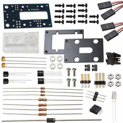
The Parallax Mouse Sensor is a module in kit form which, when assembled, provides the tracking functions of an optical mouse. The two-wire serial interface is directly compatible with the Parallax BASIC Stamp® 2 family, the Parallax PropellerTM, and other microcontrollers.
Features
Compact module, including illumination, optics, and custom laser-cut base "Close-to-the-metal" register-based serial interface for maximum flexibility Holes for mounting to other equipment Compatible with any BS2-family BASIC Stamp, the SX, and the Parallax Propeller Accommodation for single or dual three-wire (servo-type) interface cables
Power requirements: 5 VDC 35 mA Communication: Two-wire serial (clock and data) Logic compatible with 3.3V (using external resistor) and 5V microcontrollers Dimensions: 1.00" (25.4 mm) 0.65" (16.5 mm) H
Measuring X and Y displacement on a flat surface Detecting vibration in two dimensions over a flat surface
Part Parallax No. 150-01021 150-01022 Description Printed circuit board
MCS-12086 mouse sensor chip Red T1¾ LED (lens may be red or clear) Right-angle LED holder Clear plastic lens/light guide 1N5817 Schottky diode 1/8 W resistor (brown, black, red) 1/8 W resistor (brown, black, brown)
Description 100 µF aluminum electrolytic capacitor (color may vary) 0.1 µF ceramic capacitors (marked x 3 header (2mm) 2mm shunts 2x3 header (0.1") Two-piece black Delrin rectangular base set Black plastic snap rivets #2 x Phillips pan head machine screws #2 hex nuts White nylon spacers
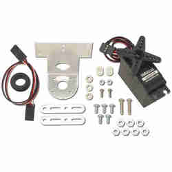
Additional Parts for Interfacing servo extension cable 3-pin header 2N3904 NPN transistor (marked 2N3904) 2N3906 PNP transistor (marked ¼ W resistors (red, red, red) ¼ W resistor (yellow, violet, brown)
· Wire clippers Needle-nosed pliers 99% isopropyl alcohol and an old (clean) toothbrush Miniature (#0) Phillips screwdriver Pointed tweezers Eye protection
Fine-tipped soldering iron and small diameter (1/32") rosin-core solder (lead-free or leaded)
· BASIC Stamp, Propeller, SX, etc. Carrier board (e.g. Board of Education, Propeller Demo Board, Propeller Proto Board, etc.) One or two servo extension cables with 3-pin headers (e.g. Parallax #805-00011)
1. The printed circuit board is marked on top with the part numbers from the "Part" column in the table above. Here is an illustration of the unpopulated circuit board:
2. Install and solder all the parts, except U1 and LED1, as shown below, paying close attention to the polarity of D1 (stripe goes to the right) and of C1 (positive lead the longer one goes to the top). Take your time and make sure that all parts are firmly seated against the board. For J1 and J2, solder the diagonal corner pins first and check the seating. If a header is crooked or not all the way in, you have a chance to reheat the joints and make adjustments. Once these headers are seated correctly, you can solder the remaining pins. Here's what the board will look like:
3. Take the LED and insert it into the right-angle holder, being sure to position the longer, positive lead as shown:
4. With the needle-nosed pliers, grab the leads and pull the LED against the holder until it's firmly seated. Then, still pulling with the pliers, bend the leads sharply downward:
NOTE: The LED is shown in the drawings with a red lens. The LED provided may be red or clear
Documentationhttps://www.parallax.com/sites/default/files/downloads/28560-Mouse-Sensor-Kit-Product-Documentation.pdf

